

Published August 2, 2026 · Updated August 30, 2026 · How we source this
How to Identify an LS Donor Engine Before You Buy: RPO, VIN, Crank/Cam Signals, Throttle & Controller

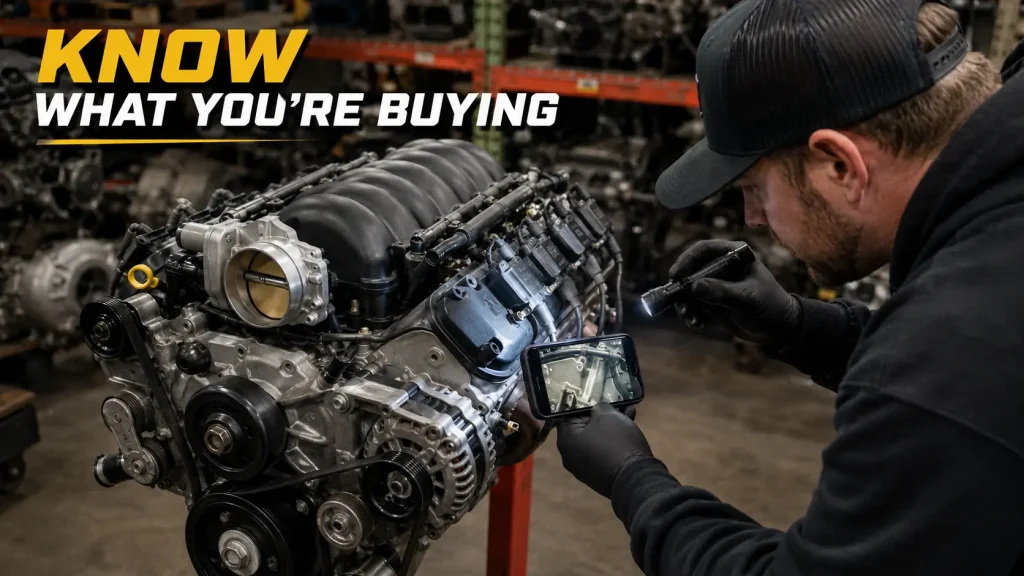
The single most expensive mistake in an LS swap is buying the wrong engine — or the right engine with the wrong electronics — because you trusted a valve cover, an intake badge, or a seller’s ad. Gen III and Gen IV LS-family engines look nearly identical across very different electrical architectures, and the parts that actually determine whether your build runs (crank reluctor, cam signal, throttle system, controller) are not visible at a glance. This page is a pre-purchase identification procedure: what to look at, in what order, and why each item matters.
Critical rule: engine generation, electronics generation, controller, crank/cam signal, throttle type and model year are separate facts. “Gen III” or “Gen IV” alone tells you almost nothing about compatibility. Identify each attribute independently and write it down before you buy.
Before you go: what you’re trying to walk away knowing
By the end of an inspection you want a written record of: the engine RPO, the donor year and vehicle, block casting/material, displacement, crank reluctor (24x vs 58x), cam signal and sensor location, throttle system (cable vs electronic), the controller/PCM on the label, the transmission RPO, the fuel-rail style, the accessory-drive family, and the oil pan. Photograph everything. The rest of this guide walks each one.
Step 1 — Find the RPO (the engine’s real name)
GM’s RPO (Regular Production Option) code — LM7, LQ4, LQ9, L96, LS3 and so on — is the most precise identifier for a production engine. On a complete donor vehicle, the full RPO list is printed on the Service Parts Identification (SPID) label, usually in the glovebox, center console lid, or driver’s door area. Match the engine code (see the reference below) against that list.
Verify before ordering: a bare engine on a pallet usually has no RPO label. In that case the RPO is an inference from the VIN, castings, and hardware — not a certainty. Treat a seller’s “it’s an LQ9” as a claim to be checked, not a fact.
If the donor is a complete vehicle, photograph the SPID label and run it through the GM RPO Decoder before you leave — it returns the meanings for that truck’s model year, so you are not working off a code that meant something else ten years earlier.
Step 2 — Decode the VIN (8th digit = engine)
On the donor vehicle’s VIN, the 8th character is the engine code. It narrows down displacement and often the specific engine family for that year. It is a strong clue but not a complete answer, because one VIN engine code can cover more than one RPO across years and platforms, and mid-year production changes are not visible in the VIN.
Application-dependent: use the VIN engine code together with the model year and platform, then confirm against castings and hardware. Do not derive crank reluctor, cam signal, throttle type or controller from the VIN alone.
Step 3 — Read the block casting number and engine ID
The block casting number (cast into the block, commonly on the rear or bellhousing flange area) and any machined engine ID confirm block family and material. This is how you separate, for example, an aluminum car block from an iron truck block when the RPO label is gone. Casting numbers change by year and material, so record the exact number and cross-reference it rather than assuming from the outside.
Step 4 — Confirm displacement and block material
Use this only as a first-pass sanity check against Steps 1–3, not as identification on its own:
- 4.8L — Gen III LR4 (iron truck); Gen IV LY2 / L20 (iron truck/van). Note: the LR4 is 4.8L, not 5.3L.
- 5.3L — Gen III LM7, L59 (flex-fuel), LM4/L33 (aluminum); Gen IV LH6, LY5, LMG, LC9, LH8, LH9, LMF, plus the transverse LS4. The LC9 is a 5.3L Gen IV engine — not a 4.8L.
- 5.7L — Gen III car LS1 / LS6 (aluminum).
- 6.0L — Gen III LQ4, LQ9 (iron); Gen IV LY6, L96, L76, LFA/LZ1 (hybrid), LC8 (alt-fuel), LS2 (aluminum car), and others.
- 6.2L — Gen IV L92, L9H, L94 (truck/SUV); LS3, L99, LSA, LS9 (car/performance).
- 7.0L — Gen IV LS7 (dry-sump, C6 Z06).
Verify before ordering: the same displacement spans very different electronics. A 5.3L could be a 24x cable-throttle Gen III LM7 or a 58x electronic-throttle Gen IV LMG — wildly different swap wiring. Keep going.
Step 5 — Crank reluctor (24x vs 58x) and crank sensor
The crank “reluctor” wheel tooth count determines which controllers and crank position sensors will work. Most Gen III engines use a 24x reluctor; most later Gen IV engines use 58x. The crankshaft position sensor sits low at the rear of the block at the bellhousing area.
Transition-year exception: generation does not guarantee reluctor count. The 2005 LS2, for example, is a Gen IV engine that still uses 24x, while the 2006 LS2 switched to 58x. Early Gen IV 5.3L applications (e.g., some LH6) also carried 24x before moving to 58x. Confirm the reluctor for the exact year/application.
Sensor colour is a clue, not proof: crank-sensor connector colours are often cited as a 24x-vs-58x shortcut. Colours are a useful hint, but they are not a substitute for verifying the reluctor and the matching controller — connector colour alone has misled many builders.
Step 6 — Cam signal (1x vs 4x) and cam-sensor location
The camshaft position signal pairs with the crank signal. Broadly, 24x systems use a 1x cam signal with the cam sensor at the rear of the block, and 58x systems use a 4x cam signal with the cam sensor moved to the front timing cover. Rear cam sensor vs front cam sensor is one of the fastest visual tells of which electronics era you’re looking at — but confirm it against the reluctor and controller rather than treating the sensor location as the whole answer.
Application-dependent: VVT (variable valve timing) engines and some transitional applications change cam hardware and timing covers. Note the sensor location and whether a cam phaser/VVT front cover is present.
Step 7 — Throttle system: cable (DBC) vs electronic (DBW)
Look at the throttle body. A drive-by-cable (DBC) throttle body has a throttle-cable bracket and linkage; a drive-by-wire (DBW / electronic) throttle body has only an electrical connector and no cable. This determines whether you need an electronic accelerator pedal, a throttle-actuator strategy, and a controller that supports it.
Throttle type is application-specific — don’t infer it from the RPO: for example, F-body LS1 packages are commonly cable while C5 Corvette LS1 packages are electronic. Most 1999–2006 truck LM7/LQ4 engines are cable; later truck engines are electronic. Verify the actual throttle body and whether a matching pedal came with the engine.
Supporting hardware required: converting an electronic-throttle engine to cable (or vice versa) is a hardware change — throttle body, TPS, IAC-capable intake or adapter, harness and controller strategy — not something a tune alone can do.
Step 8 — The controller / PCM (identify by the label, not the colour)
If the engine comes with its controller, this is one of the most valuable parts to identify. Common LS-family engine controllers include the Gen III P01 / P59 and the Gen IV E40, E38, E67 and later E78. Identify the controller by the GM service number on its label and the exact application — not by connector colour or a family nickname.
- Do not assume interchangeability from connector colour. Two controllers can share a connector colour and still have different pinouts, operating systems and feature support.
- A “family” name is not a part number. “P59” or “E38” covers many service numbers, operating systems and calibrations. Record the exact service number on the label.
- The original matched controller is often the safest starting point for a swap, because it already pairs with that engine’s crank/cam signal, throttle and transmission strategy.
Not verified / factory documentation required: do not rely on internet “blue plug / green plug” pinout charts. A pinout is only trustworthy tied to an exact controller service number, application and model year from factory service information.
Step 9 — Transmission RPO and identification
If a transmission is attached, identify it too — the automatic control architecture is part of the swap. Note whether it’s a 4L60E / 4L65E / 4L70E (medium-duty) or 4L80E / 4L85E (heavy-duty), or a later 6L80E / 6L90E six-speed, and record its RPO/ID tag. The six-speeds in particular use their own internal control module and network strategy that must match the engine controller.
Verify before ordering: “it bolts up” is not a complete compatibility answer. Bellhousing fit, flexplate/converter, input shaft, speed sensors/VSS, control module and calibration all have to line up. Record what you have and confirm each.
Step 10 — Fuel rail and injector connectors
The fuel rail is a quick indicator of fuel-system architecture. A rail with a single feed line and no return points to a returnless system; a rail with feed and return points to a return system. Injector connector style also varies by family. This matters because your OBS/Squarebody fuel plumbing has to match the rail you end up running.
Application-dependent: record the rail style and injector connector, and match your tank/pump/return arrangement to it rather than assuming.
Step 11 — Accessory drive and oil pan
The accessory drive (truck vs Corvette vs F-body/car spacing) affects belt path, clearance to your frame, steering box, and hood. The oil pan is a truck pan on truck engines and a car pan on car engines — and neither may clear your swap chassis. Photograph the front of the engine and the pan.
Verify before ordering: oil-pan fitment depends on your chassis, engine and mount position, and 2WD vs 4WD front-differential clearance — not on a “front-sump vs rear-sump” label. Plan the pan around your specific truck.
Step 12 — VVT and AFM/DOD indicators
VVT (variable valve timing) engines have a cam phaser and a specific front cover and cam sensor arrangement. AFM/DOD (Active Fuel Management / Displacement on Demand, cylinder deactivation) engines have specific lifters, a valley cover with the AFM manifold/solenoids, and a different oil-control setup. Note whether these systems are present, because you’ll decide to retain, electronically disable, or mechanically delete them — each path has different parts and tuning implications.
Never assign AFM failures to a non-AFM engine. Non-AFM engines (for example the Gen III LM7) have no AFM lifters to fail. Confirm whether a given RPO actually has AFM before assuming an “AFM problem.”
The pre-purchase photo checklist
Before you hand over money, get clear photos of: the SPID/RPO label (if a complete vehicle); the VIN; the block casting number; the throttle body (cable bracket or electrical-only); the front timing cover and whether a cam sensor is there; the rear of the block at the crank sensor; the controller label (service number); the transmission ID tag; the fuel rail; the accessory drive; and the oil pan. Those photos let you — or the FSC forum — confirm the engine before it’s in your driveway.
Reference note: any simplified identification diagrams published here are FullSizeChevy reference illustrations to show where to look — they are not GM service drawings. For exact pinouts, connector views and torque values, use factory service information for the specific year, application and controller.
Next steps
Once you know what you’re actually buying, plan the rest of the build from the LS Swap Hub. For wiring specifics, see the OBS Chevy LS Swap Wiring Harness Guide, and for engine selection start with the LS Swap Guide for Chevy & GMC Trucks. Buying used? Cross-check with the LS Engine buyer’s guide and, for a 6.2L, the Used LS3 checklist.
Talk trucks with other owners
Post your truck, your build, or the problem you are chasing and get real answers from full-size GM truck owners in the FSC forum.
Open the FSC Forum →